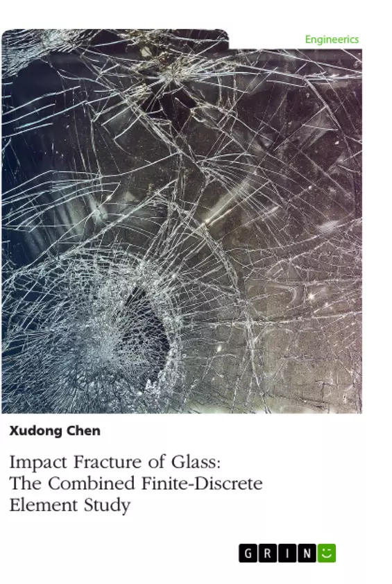
This book introduces theoretical and practical aspects for modelling the impact fracture of glass and laminated glass using the combined finite-discrete element method (FDEM). The FDEM is a branch of the discrete element method (DEM), and combines finite element formulation into individual discrete elements. Thus, contact forces are evaluated more accurately. Regarding the fracture of glass, a Mode I-based smeared crack model is extended and employed in the FDEM, enabling crack initiation and propagation be captured naturally. Based on the employed method and the crack model, numerical examples on fracture of glass under both hard and soft impacts are presented and validated with data from computational and experimental sources. The combined finite-discrete element method is proven to be a reliable and robust tool for examining the impact fracture responses of glass.
Contents
1. Introduction
1.1 Background
1.2 Structural Applications of Glass
1.2.1 Annealed Glass
1.2.2 Heat-Strengthened Glass
1.2.3 Toughened Glass
1.2.4 Laminated Glass
1.3 Summary
2. Brittleness and Rupture of Glass
2.1 Introduction
2.2 Theoretical Examination
2.3 Experimental Investigation
2.4 Computational Study
2.4.1 FEM
2.4.2 DEM
2.4.3 FDEM
3. Fracture Model of Glass
3.1 Overview
3.2 Smeared Crack Model
3.3 Strain Softening Curve
4. Monolithic Glass
4.1 Validation
4.2 Convergence
4.3 Parametric Study
4.3.1 Tensile Strength
4.3.2 Fracture Energy
4.3.3 Impact Velocity
4.3.4 Impact Angle
4.3.5 Projectile Size
4.4 Summary
5. Laminated Glass
5.1 FDEM Modelling
5.2 Interlayer
5.3 Glass-Interlayer Interface
5.4 Validation
5.5 Convergence
5.6 Young’s Modulus of Interlayer
5.7 Conclusions
6. Soft Impact
6.1 Introduction
6.2 Elastic Impact
6.3 Fracture Study
6.4 Comparison Study
6.4.1 Hard vs. Soft Impact
6.4.2 Laminated vs. Monolithic Glass
6.5 Parametric Study on Projectile
6.5.1 Impact Velocity
6.5.2 Young’s Modulus
6.5.3 Nose Shape
6.6 Conclusions
References
Acknowledgements
This book could not have happened without the supports and encouragements of the publishers and my colleagues. I would like to express my gratitude to Professor Andrew H. C. Chan, who guided, supported and advised me during my PhD study. I also appreciate Professor A. Munjiza who provided the combined finite-discrete element method program and support to me. Without their guide, support and advice, this book would not be possible.
Preface
Glass and laminated glass are commonly used for structural purposes in modern automotive industry and civil engineering. To examine the fracture and fragmentation of these glass members under impact, a novel computational approach, i.e. the combined finite-discrete element method, is employed in this book.
The combined finite-discrete element method is a special branch of the discrete element method. In this method, structures are discretised into a number of discrete elements which are connected to each other by linked interfaces. Within each linked interface, a fracture model is incorporated, controlling solids from continua to discontinua. Each discrete element interacts with those that are in contact with it. Within a discrete element, finite element mesh is formulated, resulting into a more realistic estimate of contact forces and the deformation of the structure. In view of these merits, crack initiation and propagation can be predicted more accurately, and fragments can move in a more rational manner. Since considerable fracture is involved in the impact consideration of brittle glass, the employed combined finite-discrete element method is naturally suitable for this impact fracture modelling.
A Mode I-based fracture model is extended and employed to model crack initiation and propagation in glass and laminated glass body. Different types of damages, e.g. local, cone, flexural and punching are obtained. Obtained results are validated with data from existing literature, verifying the proposed glass fracture model. Parametric studies are performed to further examine the breakage behaviour of glass and laminated glass, demonstrating the applicability of this computational technique for the analysis of glass impact mechanism.
A book on glass applications of this novel computational approach is long overdue. This book aims at assisting those who are interested in the principles, implementations and benchmarks of the combined finite-discrete element method for examining the impact fracture of glass and laminated glass.
1 Introduction
1.1 BACKGROUND
The time when humans started making glass can be traced back to around 10,000 B.C. in Egypt (Sedlacek et al., 1995). Archaeological findings (Dussubieux et al., 2010) demonstrated that in ancient times, soda lime glass was rare due to the complexity of production and lack of essential techniques. Before 1,890 A.D., the development of glass industry was slow (Axinte, 2011). Due to its transparency and resistance to chemical agents, most glass was provided for decoration and as equipment in chemistry laboratories, e.g. flasks and containers.
In the 19th century, following the invention of the Siemens-Martin firing method, massive glass production becomes possible (Sedlacek et al., 1995). This resulted in the applications of glass to windows and facades, like crystal palaces and greenhouses.
Around 1960, Sir Alastair Pilkington introduced a new revolutionary manufacturing method for float glass. This method is still in use and covers 90% of float glass production today (Axinte, 2011). Since then, float glass (or flat glass) has gained dominant market shares for windows, facades, roofs, etc. New types of glass have been introduced from time to time. During the 1970s, glass for special uses, e.g. container for radioactive material, was also available. Back to its original form, the most common application of glass is still windows glazing and facades. In nowadays construction, more and more glass components are employed for structural purposes. In the following sections, structural applications as well as different varieties of glass are introduced.
1.2 STRUCTURAL APPLICATIONS OF GLASS
In building constructions, glass is commonly used as balconies, facades and other structural members. Roof is also popular as light can pass through it freely without any obstruction. In these cases, loads such as snow, wind and self-weight are undertaken by glass members. Broadly speaking (Ledbetter et al., 2006), the term ‘glass structures’ also includes glass elements that transfer loads other than those imposed directly on to them. Examples include beams, columns, walls, balustrades, stairs, floors, bridges, etc.
Glass beams are generally simply supported or clamped. Early examples can be found in the work of Dewhurst McFarlane (Dawson, 1995) and Nijsse (1993). A notable example is the entrance canopy to the Yuraku-cho underground station in Tokyo (Dawson, 1997) which compromises four pieces of glass bolted together. Glass columns and load-bearing walls are not common due to its brittleness as they may fail in a sudden without any pre-warning. A representative example is the 13.5m high, ground-based glass wall at the Royal Opera House, Covent Garden, London (Dodd, 1999).
Due to the aesthetic appearance and transparency, more and more challenging glass applications emerged in civil engineering within the recent decades. One of the examples is the Grand Canyon Skywalk in Arizona, US. The glass observation deck of the skywalk enables the tourists to gaze deep into the abyss without any visual barriers. Besides that, four reinforced glass ‘balconies’ were attached to the Sears Tower (now Willis Tower) for visitors. With its four 10×10 square feet compartments protruding 4.3 feet from the building’s 103rd floor observation room, the platform provides a completely transparent space to generate the sensation of hovering over Chicago, US.
In industry, glass is manufactured into different products using different methods catering for different purposes. According to Axinte (2011), glass can be classified as common glass (basic and decorative) and special glass. Among these types, annealed, heat-strengthened, toughened and laminated glass are commonly used in civil engineering. These types of glass are introduced respectively in the following sections.
1.2.1 Annealed Glass
Annealed glass (or float glass) is cooled gradually from high temperature to room temperature. This process eliminates the residual stress to the maximum and allows the glass to be cut conveniently. It is the most commonly available type and also the most vulnerable type of glass (Masters et al., 2010). Large shards with sharp edges will be produced when annealed glass breaks. Penetration and collapse of the glass may occur. The failure stress of annealed glass is also relatively low. Should σ be the failure stress of annealed glass, n is a constant depends on the environment and T equals to the load duration, Sedlacek et al. (1995) gave the relationship between the failure stress and the load duration as is expressed in Eq. (1.1).
Abbildung in dieser Leseprobe nicht enthalten
The plotting of the relative failure stress versus load duration is shown in Figure 1.1. Since n =16 is normally used in building design and the characteristic bending stress is 45MPa according to EN 572-1.
Abbildung in dieser Leseprobe nicht enthalten
Figure 1.1 Relative failure strength of annealed glass (after Sedlacek et al., 1995)
1.2.2 Heat-Strengthened Glass
Heat-strengthened glass needs to experience controlled heating and cooling processes which produce a permanent compressive surface residual stress. Applying the superposition principle (Ledbetter, 2006), if the failure bending stress of heat-strengthened glass is σH, and the residual compressive surface stress is σR, an expression can be obtained in Eq. (1.2), as where σ is the strength of annealed glass mentioned previously. Obviously, the existence of the residual compressive surface stress enables the heat-strengthened glass a higher failure bending strength than that of annealed glass. EN 1863-1 requires a 70MPa characteristic strength for heat-strengthened glass. Despite its enhanced strength, the damage pattern of heat-strengthened glass is similar to that of annealed glass, producing large sharp fragments which pose potential injury to users.
1.2.3 Toughened Glass
If glass is processed in the same way as the heat-strengthened glass but is cooled more rapidly, toughened glass (or tempered glass) is obtained. It is heated in a furnace to approximately 640 Centigrade and then chilled by cold jet air. A residual compressive surface stress over 69MPa can be obtained and a higher strength for toughened glass can be achieved (characteristically 120MPa in accordance with EN 12150-1). In the event of breakage, numerous small blunt fragments will be generated, normally diced.
Sedlacek et al. (1995) pointed out that the higher the pre-stress, the higher the disintegrating force will be once the toughened glass gets damaged, and the smaller the fragments will be as a consequence. These fragments do not have sharp edges that annealed and heat-strengthened glass have, and deep cutting injuries to humans are unlikely to occur either. However, the left small fragments are not able to resist residual load once breakage occurs, resulting in a full or partial collapse of the glass.
1.2.4 Laminated Glass
Laminated glass is an assembly of glass sheets together with one or more interlayer(s) (Figure 1.2). It is manufactured in an autoclave under high temperature and pressure. In general, laminated glass can be developed from any type of glass mentioned above (annealed, heat-strengthened or toughened). The strength, breakage and post-failure behaviour of laminated glass depend heavily on the glass type, glass thickness, interlayer type and thickness. Different types of glass sheets lay different emphasises. Toughened glass is used to provide sufficient strength to resist load while annealed and heat-strengthened glass are used to govern the post-failure behaviour. Film interlayer for laminated glass is normally polyvinyl butyral (PVB) for construction and automobile but stiff resins like SentryGlas®Plus (SGP) is also prevalent in some applications (Bennison et al., 2002; Delincé et al., 2008).
Abbildung in dieser Leseprobe nicht enthalten
Figure 1.2 Typical three-layered laminated glass
The inclusion of interlayer makes the laminated glass a complicated composite material. Under sustained load, layered behaviour will be presented. For short load duration, more shear transfer can be provided. Relevant research (Behr et al., 1993; Norville, 1999) demonstrated that laminated glass behaves in a similar manner as monolithic glass with the same thickness in wind gusts.
Post-failure analysis of laminated glass is of significance. Once shattered, spider web cracks will be obtained and the interlayer will hold the broken glass fragments if there is enough adhesion. This feature is particularly important as potential injury and damage caused by sharp pieces of flying glass fragments can be minimised. Quality requirements for laminated glass can be found in some industry code, for instance, in ASTM C 1172 and EN ISO 12543.
1.3 SUMMARY
Whether it is the entrance canopy in Tokyo or the modern platform in Chicago, impact caused by dropping objects or windborne debris is always a great threat to these glass applications. Structural analysis is needed to investigate these modern, high-technique constructions. Also, fracture and fragmentation of glass will be involved in these studies due to its brittle nature. As a result, genuine dynamic analysis is vital. Obviously, traditional analytical approaches are not capable of solving such sophisticated phenomena. Experimental tests are usually performed with the support of high-speed photography, which is indispensable if transient responses are required (Baird, 1947; Salman and Gorham, 2000; Hopper et al., 2012). With the development of computer hardware and improvement of numerical algorithms, computational approach becomes a reliable and efficient tool to engineers and researchers (Flocker and Dharani, 1997b; Sun et al., 2005; Timmel et al., 2007). Numerical simulation is quite attractive due to its low cost and high manipulability.
The most commonly used software for analysing engineering problems is based on the finite element method (FEM) (Clough, 1960; Zienkiewicz and Taylor, 1967). The FEM excels in solving continuum problems but is considered not to be so helpful for discrete modelling. These discrete problems usually involve large non-linear displacements and considerable number of moving bodies. Although some progress has been achieved in the extended finite element method (XFEM) and showed the applicability to cracks (Areias and Belytschko, 2005), it is still difficult to solve these issues mentioned above. For discrete problems, typically the fracture of glass followed by numerous fragmentation and interaction, the best choice is to use the discrete element method (DEM). The combined finite-discrete element method (FDEM) is a special branch of the DEM family with the combination of both FEM and DEM techniques. It is originated from Swansea University (Munjiza, 1992; Munjiza and Bicanic, 1994) and an accompanying open source code ‘Y’ has been developed (Munjiza, 2000). In this method, each element is a discrete element, making the method quite capable of predicting discrete behaviour. Within a discrete element, a finite element formulation is embedded, providing a more accurate estimate of contact forces and deformation of fragments. The FDEM can be considered as a discrete element method combining with finite element formulations. Further details on the FDEM are introduced in Chapter 2. It is a useful tool for structural engineers to understand the behaviour of glass under impact. Based on the knowledge of damage process, a safe and robust design could be produced and contribution to the industry can be made.
This book presents the modelling of the impact fracture behaviour of glass using the combined finite-discrete element method (FDEM). Layout of the rest chapters are as follows. Chapter 2 summaries the current study on the rupture of glass due to its brittle nature. Investigations from theoretical, experimental and computational aspects are addressed. Chapter 3 introduces the fracture model of glass used in the FDEM modelling. Chapter 4 and 5 cover the impact responses of both monolithic and laminated glass, respectively. Some results from the FDEM modelling are presented. Chapter 6 focuses on soft body impact, and differences between soft and hard body impacts are illuminated.
2 Brittleness and Rupture of Glass
2.1 INTRODUCTION
As a transparent material, glass is increasingly used despite its brittle nature. The role of glass in buildings is moving forward from non-structural elements (windows and facades) to load-bearing components (beams, staircases, balconies, etc.). The glass squash court (Hill, 1982) in early 1980s set off the research on the structural properties of glass.
Although structural applications of glass become popular in recent decades, research on the damage of glass enjoys a long history. Preston (1926) demonstrated that the manner of breakage in annealed glass is directly related to the appearance of fracture surfaces. This view was supported by Murgatroyd (1942) and Shand (1954). Some of the general fracture features in glass were described by many other researchers (Holloway, 1968; Clarke and Faber, 1987; Ward, 1987).
Fracture of glass also plays an important role in other areas besides civil engineering. For forensic interpretation, the earliest record on blunt-impact window fracture was published by Russian criminologist Matwejeff (1931). McJunkins and Thornton (1973) also stated in their review that glass fragments caused by impact are usually reconstructed for criminal investigation. This was further verified by Haag and Haag (2006) on the bullet impact on glass. In aeronautics, hypervelocity impacts at the magnitude of km/s on glass was taken into account. A review by Cour-Palais (1987) presented the research performed during Apollo lunar missions between 1960s and 1970s. As to the development, a damage equation was given by Taylor and McDonnell (1997) and oblique hypervelocity impacts on thick glass targets were also studied (Burchell and Grey, 2001). Automotive industry investigates the fracture of glass intensively for the safety of vehicle users. Timmel et al. (2007) investigated the behaviour of windscreen failure subjects to external projectile. On the other hand, human head impact on windshields is also a major consideration for safety control (Zhao et al., 2006b).
In civil engineering, glass is commonly used for balconies, facades and other structural elements. In practice, glass have to endure load from wind, blast, impact, etc. Research on the blast and pulse pressure loading posed on glass (Goodfellow and Schleyer, 2003; Norville and Conrath, 2006) provided an effective design guide for reducing human injuries. Minor and Norville (2006) studied the influence of lateral pressure on glass and a relevant design guide was given. In the work of various researchers (Rao, 1984; Calderone and Melbourne, 1993), glass behaviours under wind loads were investigated, providing significant usefulness to high buildings and wind-prevalent areas. Regarding the impact, Minor (1994) indicated the responses of building glazing subjects to windborne debris impact, including both small and large projectiles. The stress and safety for ordinary (annealed) glass liable to human impact (Toakley, 1977) was also discussed in order to minimise potential injuries.
Since the monolithic glass is vulnerable under impact and other external effect, laminated glass is investigated and employed in industry. Early studies on laminated glass plate were carried out experimentally (Behr et al., 1985; Behr et al., 1986; Vallabhan et al., 1993). Some examinations on laminated glass beam (Hooper, 1973; Norville et al., 1998) were also performed. Shutov et al., (2004) experimentally investigated laminated glass plates with different laminated strategies (three glass plies with two interlayers; two glass plies with one interlayer and one outerlayer; two glass plies with one interlayer). All the research indicated that laminated glass can significantly absorb impact energy and prevent a projectile from penetrating. Meanwhile, numerical simulations using FEM were also carried out. Research from Flocker and Dharani (1997a), Du Bois et al., (2003) and Timmel et al., (2007) also demonstrated that laminated glass has better energy absorption capacity than monolithic counterparts.
As is seen in civil engineering, responses of glass subject to impact is important. Since its brittleness leads to crucial issues, the fracture of glass has been widely and intensively investigated. The traditional elastic theories (Love, 1892; Timoshenko and Prokop, 1959) which based on continuum assumptions will no longer be applicable to these discrete phenomena where fracture is involved. Developments call for new theory with regard to its fracture.
2.2 THEORETICAL EXAMINATION
As an ideally brittle material, glass neither exhibit sufficient ductility nor provide noticeable pre-warning before damage occurs. Referring to its stress-strain curve, glass does not exhibit any yielding either (Figure 2.1).
Theoretically, the fracture of glass has to obey some physical laws. One of the theories is the Linear Elastic Fracture Mechanics (LEFM). Although modern microscopic technique asserted that the essence of fracture is the breakage of the bonds between atoms, the cause of fracture was largely a mystery over a considerable period in history.
Abbildung in dieser Leseprobe nicht enthalten
Figure 2.1 Stress-strain curves of glass (after Sedlacek et al., 1995)
Abbildung in dieser Leseprobe nicht enthalten
Figure 2.2 An elliptical crack in a plate subject to remote tensile stress
Love (1892) remarked in his elasticity text that ‘the conditions of rupture are but vaguely understood’, however, the era of fracture from a scientific point of view was coming. In 1920, pioneering work on the quantitative connection between fracture stress and flaw size was published by Griffith (1920) and concluded in his later work (Griffith, 1924). He analysed the stress around a through-thickness elliptical flaw in an infinite elastic plate with crack length 2 a, Young’s modulus E and surface energy 2 γ (Figure 2.2). The analysis was made based on an experiment performed by Inglis (1913) to consider the unstable propagation of a crack, and remote tensile stress σ perpendicular to the major axis of the ellipse is applied.
Griffith’s model gave the propagation criterion for an elliptical crack and solved the fracture stress σ f as is given in Eq. (2.1).
It also correctly predicted the relationship between strength and flaw size in glass specimens. Since the model considers that work for fracture comes exclusively from surface energy, Griffith’s approach only applies to ideally brittle materials. Further, as it assumes that the brittle material contains elliptical microcracks, high stress concentration was also introduced near the elliptical tips. In addition, a large gap in mathematical derivation of Griffith’s work was left, where details can now be found from other research (Hoek and Bieniawski, 1965; Jaeger and Cook, 1969).
Shortly after the Second World War, Irwin (1957) extended Griffith’s model and introduced a flat crack instead of an elliptical one. This flat crack is more realistic in engineering problems and suitable for arbitrary cracks (Anderson, 1991; Ceriolo and Tommaso, 1998). It is worth mentioning that although Irwin developed Griffith’s model, the singularity at the crack tip still exists. This is not correct in reality as no stress should exist at free surfaces.
In Irwin (1956), the concept of strain energy release rate was developed. Energy absorbed for cracking must be larger than the critical value to create a new crack surface. If we set in Eq. (2.1), the critical state can be obtained in Eq. (2.2).
Furthermore, according to Westergaard (1939), Irwin showed that stress field in the area of crack tip can be completely expressed by the quantity K, namely the stress intensity factor. K is usually given a subscription of I, II or III to denote different modes of loading (Figure 2.3). In fracture mechanics (Knott, 1973; Barsom, 1987; Anderson, 1991), Mode I is for the principal load normal to the crack plane, leading to open the crack. Mode II and III are shear sliding modes and tend to slide one crack face with respect to the other, but in different planes. It is widely held that Mode I fracture is the most common and dominant type for brittle fracture. The ascertain has been supported by Anderson (1991) and many other researchers.
Abbildung in dieser Leseprobe nicht enthalten
Figure 2.3 Three modes of fracture loading (after Zimmermann et al., (2010))
Concerning further theoretical developments on fracture mechanics, Rice (1968) developed a new parameter, J -integral, which is independent of the integration path around the crack tip. It is known that the J -integral is equivalent to the energy release rate in the analysis of fracture mechanics for brittle solids in LEFM.
The fracture mechanics developed gradually from Griffith approach to cohesive models. Before the prominent Hillerborg’s model (Hillerborg et al., 1976), some researchers attempted to include the cohesive forces into the crack tip region in order to solve the stress singularity introduced in Irwin’s model. Barenblatt (1959, 1962) assumed that cohesive forces exist in a small cohesive zone near the crack tip and enable the crack face close smoothly. However, the distribution of these cohesive forces is unknown. Dugdale (1960) held the same hypothesis as Barenblatt’s but considered the closing force is uniformly distributed (Figure 2.4) for elastic-perfectly plastic materials.
Abbildung in dieser Leseprobe nicht enthalten
Figure 2.4 Uniform distribution of cohesive force at crack tip (after Dugdale (1960))
Although Barenblatt’s and Dugdale’s models proposed the concept of a cohesion zone, they still differ from the model of Hillerborg (1976) from several important aspects (Figure 2.5).
Abbildung in dieser Leseprobe nicht enthalten
Figure 2.5 Stress distribution and the strain softening curve (after Hillerborg (1976))
One of these differences is that Barenblatt and Dugdale both assume a pre-existed crack in the analysis, while Hillerborg included the tension softening process through a fictitious crack. Thus, there are two zones in Hillerborg’s model: a real crack where no stress transfer and a damaging zone where stress can still be transferred. As a turning point, this model successfully achieved the crack transition based on the strain softening and can be implemented conveniently. Its variation (Bazant, 1976; Bazant and Cedolin, 1979) considers that the closed fracture processing zone can be represented through a stress-strain softening law, making itself suitable for finite element analysis.
Although the models described above are mostly based on Mode I loading conditions, reviews and surveys on brittle fracture in compression could also be found in many references (Adams and Sines, 1978; Logan, 1979; Horii and Nemat-Nasser, 1986; Guz and Nazarenko, 1989a, 1989b; Myer et al., 1992). Pure compression cannot fracture material as the inter-atomic bond must be stretched to enable fracture. According to Wang and Shrive (1995), no fracture will occur if material is loaded under hydrostatic compression. There is evidence (Wang and Shrive, 1993) showing that the initiation and extension of a crack under compression must involve Mode I crack propagation, or Mode I plus one or more shear sliding types. Wang and Shrive (1993) insisted that despite significant differences in compression and tension, the dominant mechanism of brittle fracture in compression is still Mode I cracking.
Direct observations (Costin, 1989) suggested that cracks from the pre-existing flaws propagate predominantly as Mode I fracture. Lajtai (1971) stated that the propagation of tension cracks is the most noticeable event in a compression test. Later research (Lajtai et al., 1990) also claimed that Griffith’s theory is still fundamental to all investigations of brittle solids. This has been further verified by recent research investigations (Ougier-Simonin et al., 2011). Consequently, Mode I cracking is still dominant and needs the most emphasis even in compression.
Thanks to the scientific efforts starting from Griffith in 1920s, the theoretical fundamentals for fracture mechanics now is approaching maturity. However, pure theoretical analysis is difficult to be applied to sophisticated structures. Some (the Griffith’s and Irwin’s model) still assume pre-existing cracks, which limited their applications. The limitation of LEFM is obvious that it can only solve fracture initiation.
2.3 EXPERIMENTAL INVESTIGATION
Experimentation is a traditional and vibrant approach to explore the unknown. With specimen under genuine test conditions, the advantage of experimentation is obvious. For static and quasi-static indentation, fracture patterns are provided; for dynamic considerations, drop-weight test is commonly used for low velocity impact; for impacts with higher loading rates, Hopkinson bar test are discussed.
Abbildung in dieser Leseprobe nicht enthalten
Figure 2.6 Hertzian cone crack formed by blunt indentation (after Roesler (1956))
Tracing back to the late 19th century, Hertz (1896) initially observed that a cone crack (Figure 2.6) will be generated when a hard spherical indenter is pressed normally into a brittle material. Later, Huber (1904) gave a detailed discussion on the stress distribution for the contact between two elastic spheres or between a sphere and a half-space. However, this analysis just gives an accurate prediction of the stress distribution in the glass plate before fracture begins. As long as a new fracture surface is formed, stress will be redistributed and Huber’s approach is not applicable any longer. Although the stress distribution before the elastic limit has roughly been solved, Hertzian indentation as well as the cone crack has received considerable attention from various researchers (Tsai and Kolsky, 1967; Johnson et al., 1973; Hills and Sackfield, 1987; Warren and Hills, 1994; Geandier et al., 2003). Elaguine et al. (2006) performed experimental investigation of a frictional contact cycle between a steel spherical indenter and flat float glass. And this has further been studied for different geometries and contacting materials by Jelagin and Larsson (2007).
Albeit Hertzian contact has been widely studied, other forms of crack are also available under different circumstances. Cook and Pharr (1990) summarised general crack types generated in the surface of glass by indentation contact: cone, radial, median, half-penny and lateral (Figure 2.7).
Abbildung in dieser Leseprobe nicht enthalten
Figure 2.7 General types of crack subject to indentation (after Chen (2012))
In Cook and Pharr (1990), both blunt and sharp indenters were used in the experimental test and the whole process, from loading to unloading, was observed and recorded with the aid of high-speed camera and optical techniques. Peak load of 40N has been used in their study, and glass fracture behaviour under higher peak loads has been examined by other researchers (Lawn and Swain, 1975; Lawn et al., 1980) The crack types (near-cone and median vent cracks) subject to indentation were also discussed and concluded in some further research (Komvopoulos, 1996; Gorham and Salman, 1999; Park et al., 2002) with a variety range of loads.
Although glasses are commonly tested using the Hertzian or Vickers indentation (Fisher-Cripps, 2007; Le Bourhis, 2008), the disadvantages of these conventional methods are obvious: Hertzian indentations are difficult to realise in a normal laboratory (Bisrat and Roberts, 2000). There are evidences (Quinn and Bradt, 2007; Kruzic et al., 2009) showing that indentation is not appropriate for the measurement of any basic fracture resistance. Static or quasi-static indentation cannot reflect the real dynamic response and such local damage cannot reflect a real carrying capacity of the material (Gogotsi and Mudrik, 2010).
Abbildung in dieser Leseprobe nicht enthalten
Figure 2.8 Strain-rate regimes according to loading rate (s-1)
According to Field et al. (2004), a range of strain rates span 16 orders of magnitudes from creep to impact (Figure 2.8). Early in the 19th century, people were increasingly aware that material properties and behaviour of specimen under impact differs greatly from those under static or quasi-static loading (Young, 1807; Hopkinson, 1872). As a solution, series of impact tests were conducted throughout the past decades.
Ball (or sphere) impact tests have been widely investigated (Andrews, 1931; Tillet, 1956; Tsai and Kolsky, 1967). Knight et al (1977) studied the impact of small steel spheres on soda-lime glass surface under the velocities varying from 20 to 300m/s. During loading and unloading cycles, a number of failure patterns (cone, median, radial and lateral cracking) were obtained and discussed. Ball and McKenzie (1994) performed low velocity (ranging from10 to 50m/s) steel ball impact tests on circular annealed glass plate with thickness between 3 and 12mm. Grant et al. (1998) experimentally studied four types of impact damage under low velocity impacts, calling (a) surface crushing; (b) star cracking; (c) cone cracking and (d) combined damage. Salman and Gorham (2000) investigated the fracture behaviour of soda-lime glass spheres in the diameter range of 0.4~12.7mm and concluded that at lower velocities, Hertzian ring and cone crack system will be typical while higher impact velocities lead to fragmentation arising from radial, lateral and median cracks. However, no clear boundary between low and high impact velocities was given in their research. Chai et al. (2009) employed sharp and spherical tip projectiles in investigating the crack propagation and chipping in layered glass.
Besides the drop impact tests, launching projectiles to glass specimen is also a common method to investigate its mechanical behaviour. Most early laboratory work was performed on monolithic glass subject to small hard projectile impacts. Glathart and Preston (1968) observed two major damage modes for monolithic glass plate in their research: (1) Hertzian cones will appear on the upper surface outside the contact zone if the thickness of the plate is large; (2) Glass breaks on the lower surface underneath the contact centre if the thickness of the plate becomes small. This demonstrated that the propagation of the cone crack depends largely on enough dimension along the thickness, otherwise local bending damage will be dominant. Minor et al. (1978) also reported small projectile impact tests for monolithic glass panels. The influences of glass thickness and type were studied for various geometries and projectile masses. Their study found that toughened glass shows higher resistance to impact than annealed glass due to higher residual stresses, which was also supported by Varner et al. (1980) in their experimental work.
The behaviour of laminated glass subjected to small projectile impacts at low velocities (<10m/s) was investigated by Flocker and Dharani (1997a). Results showed that Hertzian cone crack was the primary concern in these cases. With the impact velocity increases to 30~40m/s, fractures will occur in both outer and inner glass plies (Behr and Kremer, 1996). The main difference in fracture pattern between monolithic and laminated glass is that laminated glass can hold the inner glass layer while monolithic cannot.
Abbildung in dieser Leseprobe nicht enthalten
Figure 2.9 Three possible crack initiation regions (after Dharani et al. (2005))
For soft impact, failure modes depend on the flexural stress. Crack initiations are mainly situated at three possible regions A, B and C defined by Dharani et al. (2005). Region A: outside of the contact area; Region B: close to the centre of the interface between the impact side glass panel and the interlayer; Region C: the centre of the external surface of the non-impact side glass panel (Figure 2.9). Dharani and Yu (2004) conducted global-local stress analysis and illustrated that the shape of the contact surface will influence the failure mode. For spherical contact surface, crack initiates from Region B while it will start from Region C for flat ones.
Back to the early 20th century, Hopkinson (1914) invented a ballistic pendulum method to determine the pulse response caused by impact of bullets or detonation of explosives at one end of a long rod. This device as well as its variations is called the Hopkinson pressure bar. Later, researchers (Taylor, 1946; Kolsky, 1949) perceived the idea of using two Hopkinson pressure bars to measure the dynamic response of specimen in compression, which is called the split Hopkinson pressure bar (SHPB). The original SHPB was schematically shown in Figure 2.10.
Abbildung in dieser Leseprobe nicht enthalten
Figure 2.10 Diagram of the split Hopkinson pressure bar (After Kolsky (1949))
More details on this testing method can be found in many research works (Lindholm, 1964; LeBlanc and Lassila, 1993; Field et al., 1994, 2004). As an application, Bouzid et al. (2001) verified their fracture model using the SHPB test and observed the fracture patterns under high strain rate.
Since the drop ball test is constrained by the height of dropping distance, there is a limit for the impact velocity that can be reached under normal laboratory conditions. For 5m dropping distance, the impact velocity is 9.9m/s and for 10m, this value will be 14m/s. For the SHPB test, higher impact velocity can be achieved easily as it does not depend on the height limit of laboratory. Thus, the drop ball test is suitable for low velocity impacts while SHPB is more applicable to higher velocity impacts.
2.4 COMPUTATIONAL STUDY
The advantages of experimentation are apparent: direct and genuine. However, it also has some disadvantages. Carrying out experimental tests are usually time consuming and expensive. They are not easy to control and most impact tests need the support of optical techniques such as high-speed cameras. Due to initial sensitivities, responses of specimen may be unrepeatable and subject to random errors which make prediction difficult. With the modern development of computer hardware and software, numerical simulations become more and more prevalent.
2.4.1 FEM
The finite element method (FEM) was named in the work of Clough (1960). After that, the methodology of FEM developed rapidly and major developments have been illustrated in later reviews (Clough, 1979; Zienkiewicz and Taylor, 1967; Zienkiewicz, 1995). Modern technologies, such as mesh-adaptivity, were combined into the FEM and fracture models were investigated by many researchers (Carranza et al., 1997; Khoei et al., 2012; Schrefler et al., 2006). Although the FEM has been widely used in computational analysis of fracture mechanics, modelling of discrete crack configurations as well as their growth is laborious. Moving discontinuity needs the update of mesh to match the newly created geometry surfaces. Moreover, singularity at the crack tip needs accurate representation by the approximation (Tong and Pian, 1973). Methods for effective crack solving were not proposed until late 1990s.
Several new FEM-based-techniques were developed to model cracks and crack growth, including those proposed by Oliver (1995), Rashid (1998), etc. Belytschko and Black (1999) introduced a new procedure for solving cracks. In their method, remeshing is minimised by refining the elements near crack tips and crack surfaces. Partition of unity (PU) method (Melenk and Babuska, 1996) was employed to account for the presence of cracks. Moes et al. (1999) published a more straightforward technique. In their research, discontinuous fields and the near tip asymptotic fields were incorporated into a standard displacement-based approximation, allowing independent representation of the entire crack away from mesh. This extended displacement interpolation was given in Eq. (2.3), with addition of Heaviside enrichment term and crack tip enrichment term to the conventional finite element shape function.
Later, Daux et al. (2000) introduced the concept of junction function to enable the representation of branch cracks and named their method the extended finite element method (XFEM). Using XFEM, Sukumar et al. (2000) investigated mode I cracks in three dimensions. Dolbow et al. (2000) studied the fracture behaviour of Mindlin plates and 2D crack growth with frictional contact (Dolbow et al. 2001). Xu et al. (2010) analysed the windshield cracking subject to low-velocity head impact based the XFEM and both radial and circumferential cracks were characterized.
Almost at the same time, another approach called the generalized finite element method (GFEM) was introduced by Strouboulis et al. (2000a, 2000b, 2001) and Duarte (2000). This method embedded analytically developed or numerically computed handbook functions into classical FEM to improve the local and the global accuracy of the solution. According to Karihaloo and Xiao (2003), the p -adaptivity is considered in GFEM and accurate numerical simulations with practically acceptable meshes can be provided by enlarging the finite element space with analytical or numerically calculated solution of a given boundary value problem (BVP). On the other hand, XFEM pays more attention to the creation of nodes to model the new surface boundary, making it solution-dependent and more flexible.
There is a lot of work on the fracture and crack modelling using the FEM. Setoodeh et al. (2009) performed low velocity impact analysis on laminated composite plates, with 3D elastic theory coupled with layer-wise FEM approach. Liu and Zheng (2010) reviewed the recent development on composite laminates damage modelling using finite element analysis. Barkai et al. (2012) calculated the crack path in brittle material using quasi-static FEM.
For numerical simulation of glass and laminated glass fracture, usually appropriate failure models were incorporated into the FEM package, such as the continuum damage mechanics (CDM) model (Sun et al., 2005; Zhao et. al., 2006b), the fracture mechanics approach (Dharani and Yu, 2004), the two-parameter Weibull distribution (Dharani et al., 2005), etc. Pyttel et al. (2011) presented a fracture criterion for laminated glass and implemented it into an explicit finite element solver. The crack initiation is based on the critical energy threshold while propagation is related to ‘local Rankine’ (maximum stress). The FEM have been applied in predicting cracks and crack growth with reasonable accuracy, however, they are still subjected to restrictions of the FEM itself. One of the disadvantages is that post-damage discrete fragments and movement of them, which is a major concern in glass design industry, are difficult to be simulated by the FEM.
2.4.2 DEM
The discrete element method (DEM) is a method proposed for discontinuous analysis. The method was pioneered by Cundall and Strack (1979) for the study of the behaviour of 2D soil slope stability. Newton’s second law of motion was employed and kinetic equations were built in the DEM. Some discrete elements were assumed to be rigid, represented by the rigid-body-spring model of Kawai (Kawai, 1977; Kawai et al., 1978), while deformable 2D and 3D discrete elements were available from the research of Hocking et al. (1985) and Mustoe (1992). Most discrete elements are of the shape of circles in 2D and spheres in 3D, which are convenient for analysing collapse as these shapes have been widely used in granular analysis (Cundall and Hart, 1992; Griffiths and Mustoe, 2001; Robertas et al., 2004; Scholtes and Donze, 2012). Other element types (e.g. hybrid Kirchhoff element) were used according to Hocking (1992), which has been applied for simulating the fragmentation of ice sheet-conical off shore structure interaction (Figure 2.11). Similarly, cubic elements were also used in modelling collapse of discontinuous columns (Jin et al., 2011).
Abbildung in dieser Leseprobe nicht enthalten
Figure 2.11 DEM modelling of ice sheet-off shore structure interaction (after Hocking (1992))
Owen and his co-workers (Klerck et al., 2004; Owen et al., 2004; Pine et al., 2007) developed some DEM-based crack models. Klerck et al. (2004) and Pine et al. (2007) simulated the fracture in quasi-brittle materials, such as rock. Their models were based on a Mohr-Coulomb failure surface in compression and three independent anisotropic rotating crack models in tension. In Owen et al. (2004), a model for multi-fracturing solids was presented and a combination of both continuous and discrete media was considered. It should be noted that the so-called ‘discrete/finite element combination’ in their text is not the same idea of the combined finite-discrete element method which will be discussed shortly and be used throughout the analysis of this book. Instead, the terminology represents for the discrete and continuous media, respectively, and a coupled dynamic interaction between them is considered.
The same idea of the coupling was also used in the Livermore Distinct Element Code (LDEC), which was originally developed by Morris et al. (2003). In Morris et al. (2006), the code was used to simulate the fracture and fragmentation of geologic materials, like rocks (Figure 2.12).
Abbildung in dieser Leseprobe nicht enthalten
Figure 2.12 A tunnel collapse simulation by using the LDEC (after Morris et al. (2006))
Abbildung in dieser Leseprobe nicht enthalten
Figure 2.13 DEM simulations of glass fracture (after Zang et al. (2007))
The DEM simulation of glass subject to impact is not common. Oda et al. (1995) employed the DEM to simulate the impact behaviour of laminated glass. Later, they extended their research to bi-layer type of glass (Oda and Zang, 1998). Impact behaviour of both single and laminated glass subject to ball impact was studied by Zang et al. (2007), and penetration as well as the following fragmentation was simulated. In their research, both glass and PVB elements are of circle shapes, resulting in non-realistic fracture patterns (Figure 2.13).
2.4.3 FDEM
The combined finite–discrete element method (FDEM), which belongs to the discipline of computational mechanics of discontinua, is a newly developed numerical method aims at investigating failure, fracture and fragmentation in solids. The method was pioneered by Munjiza (Munjiza et al., 1995) during 1990s. According to the definition (Munjiza et al., 2004), the major difference to DEM is that finite element formulation is used to discretise the contacting domains, thus discretised contact solutions (Munjiza et al, 1997) are used for both contact detection and contact interaction. Since finite element formulation is introduced into the discrete elements, the estimate of structural responses can be more accurate. Meanwhile, penalty function is used to better control the contact force, fracture behaviour, penetration, etc (Munjiza and Andrews, 2000).
Munjiza et al. (1995) discussed the issues involved in the FDEM from a theoretical point of view and related algorithmic considerations. Later, Munjiza and Andrews (1998) proposed a No Binary Search (NBS) method for contact detection, which greatly improved the CPU efficiency and RAM requirements. The fracture model in the FDEM, which is a combined single and smeared crack model, was discussed by Munjiza et al. (1999). However, the model was limited to Mode I loading cracks of concrete and a relatively fine mesh is required to obtain accurate fracture patterns. Details on the influence of mesh size was presented by Munjiza and John (2002), giving the approximate length of plastic zone Δ so that reasonable size of elements can be meshed around the crack tip, making the stress representation more accurate within that zone.
The basis of the FDEM was published by Munjiza (2004). The accompanying open-source demonstration program is named ‘Y’, which is with the same pronunciation of ‘why’, encouraging the users to explore the unknown.
Although there are some applications of the FDEM in geologic engineering and molecular dynamics, most of them focus on the fracture behaviour of concrete and rock (Lisjak and Grasselli, 2010) and individual collision and movement of molecules (Rougier et al., 2004). Limited attention has been given to the impact damage of glass (Munjiza et al., 2013). The author (Chen, 2013; Chen et al., 2016; Chen and Chan, 2018a; Chen and Chan, 2018b) successfully simulated the impact fracture and fragmentation of single and laminated glass under both hard and soft body impact using the FDEM, with the acquisition of reasonable crack patterns, e.g. flexural and Hertzian cone cracks.
The current FDEM program costs considerable time to execute. Regarding the performance, Wang et al. (2004) analysed the parallel computation of the FDEM on PC clusters by adopting a dual-level decomposition scheme and achieved a good speed-up ratio. MPI strategy for 2D FDEM program was also being implemented by Lukas and Munjiza (2010).
Abbildung in dieser Leseprobe nicht enthalten
Technically, the FDEM is a numerical method to analyse mechanics of solids while considering it as a combination of both continua and discontinua. In this method, the deformability and stress of each single discrete element is described by a standard continuum formulation (FEM) while the contact and motion of elements are considered by discontinua equations (DEM).
For a single discrete element i, translational and rotational motions are controlled by the net external force Fi and torque Ti respectively according to Newton’s second law of motion.
Abbildung in dieser Leseprobe nicht enthalten
In Eq. (2.4) and (2.5), mi is the mass of discrete element i; ri is its position; Ii is the moment of inertia and ω i is the angular velocity. Explicit numerical integration determines the velocity and position of a particular discrete element.
Abbildung in dieser Leseprobe nicht enthalten
Figure 2.14 Contact force in the FDEM.
Contact algorithm, which can be classified as contact detection and contact interaction, is the central of the FDEM. Contact detection is a particular research domain of DEMs and beyond the scope of this book. The Munjiza-No Binary Search (NBS) algorithm is employed in the current FDEM so that computational time is linearly proportional to the number of elements involved in the simulation. Full details on the Munjiza-NBS contact detection algorithm can be referred to Munjiza and Andrews (1998). Once contact detection is completed, contact interaction follows where contact forces are defined according to the interaction law. In the FDEM, distributed contact forces are adopted for two discrete elements in contact. For the pair of discrete elements in contact, one is denoted as contactor, and the other is target. In 2D, contact forces between elements are evaluated by the overlapping area S (Figure 2.14). The penetration of any elemental area dA of the contactor into the target results in an infinitesimal contact force d F (Munjiza, 2004) where P c and P t are the points share the same coordinate on S belonging to the contactor and the target, respectively; φ c and φ t are potentials for the contactor and the target, respectively; Ep is a contact penalty parameter, and grad represents for the gradient. By integrating over the area S, the 2D contact force F is obtained in Eq. (2.7).
The corresponding 3D contact force can be simply extended by replacing the overlapping area S in Eq. (2.7) with an overlapping volume V.
3 Fracture Model of Glass
3.1 OVERVIEW
There are various models proposed to describe the damage behaviour from fracture mechanics, such as the stress intensity factor approach (Irwin, 1956), the ‘strip-yield’ model (Dugdale, 1960) and the cohesive force model (Barenblatt, 1959, 1962).
Irwin (1956) developed the concept of stress intensity factor when he extended the elliptical flaw to line crack from Griffith (1920). The stress intensity factor approach studied the stress near the crack tip and the stress will theoretically be infinite at the crack tip according to Eq. (3.1). where r is the distance to the crack tip and K is the stress intensity factor. Anderson (1991) listed some expressions of K under different types of loading. When K reaches the critical value Kc, the crack propagates. This method only applies to some simple cases as it is difficult to get a closed form solution of K for complicated specimen dimensions and loading types. Moreover, the stress at the crack tip is singular, which limits the application of this method.
Abbildung in dieser Leseprobe nicht enthalten
Dugdale (1960) developed a model suitable for elastic-plastic fracture in ductile material, e.g. metal. A plastic zone with a stress distribution equals to the yield strength is assumed near the crack tip. Barenblatt (1959, 1962) proposed a similar model to Dugdale’s but with variable stress distribution in relation with the deformation near the crack tip. Both methods define a fracture process zone (or cohesive zone, see Figure 3.1) and belong to the classification of cohesive model.
[...]
- Quote paper
- Xudong Chen (Author), 2019, Impact Fracture of Glass. The Combined Finite-Discrete Element Study, Munich, GRIN Verlag, https://www.grin.com/document/505219
-
Upload your own papers! Earn money and win an iPhone X. -
Upload your own papers! Earn money and win an iPhone X.